

Design and Construction
Facet Lube Oil Conditioners are built in carbon steel, epoxy painted and designed according to ASME VIII-I.
This equipment is specially designed to remove solids such as dirt, rust, sand and metallic particles wear, as well as lube oily water.
The equipment is made up by a separator filter, a pumping unit and heating unit (optional), all assembled in a skid.
The microfilter separator includes coalescer and separator cartridges with a double objective of retaining the finest particles and removal of water, to ensure a long life and high effectiveness thanks to their specific properties.
Lube Oil Conditioners Characteristics
The equipment has the following elements:
• Microfilter separator
• Pumping unit
• Heating (optional)
• Differential pressure gauge
• Level water gauge
• Automatic air eliminator
• Level prove to detect the presence of water
• Control panel
The control panel has the following visual alarms: high level of water in the microfilter separator, high differential pressure, general failure, high temperature alarm (optional)
Lube Oil Conditioners Results
• Removes, in continuous operation, solids and free water up to concentrations below 20 ppm
• Automatic operation, controlled by a PLC
• No flow inlet adjustment is required
• Its design ensures a safe service and free of leaks or discharges
• Their features make this equipment to have a low maintenance and to be easy to operate
• Each equipment is tested before its shipment to
ensure optimum start-up and highest service rates
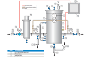
| ITEM | DESCRIPTION |
| 1 | VCS Microfilter Separator |
| 2 | Relief Valve |
| 3 | Manual Vent |
| 4 | Air Eliminator |
| 5 | Check Valve |
| 6 | Temperature Indicator |
| 7 | Differential Ppressure Gauge |
| 8 | Level Indicator |
| 9 | Level Probe |
| 10 | Inlet/Outlet Sample Probe |
| 11 | Flow Switch |
| 12 | Manual Drain Valve |
| 13 | Control Panel |
| 14 | Motor Pump |
| 15 | Inlet |
| 16 | Outlet |
| 17 | Electrical Line (customer supply) |
| 18 | Heater (optional) |
| 19 | Return to Tank Line |
| 20 | Drain |
Lube Oil Conditioners Model
| MODEL | V40 | V70 | V110 |
| Coalescer cartridge | CA56-3 | CA43-3 | CA43-3 |
| No. of cartridges | 2 | 3 | 4 |
| Recommended spares | 2 | 3 | 4 |
| Separator cartridges | ST640FD | ST636FD | ST636FD |
| No. of cartridges | 1 | 2 | 3 |
| Recommended spares | 1 | 2 | 3 |
Lube Oil Conditioners Dimension
| MODEL | DIMENSIONS | FLOW RATE | CONNECTIONS | |||||||||
| Length | Width | Height | ||||||||||
| in | mm | in | mm | in | mm | gpm | lpm | A (Inlet) | B (Outlet) | C (Return to tank) | D (Manual drain) | |
| V40 | 531∕32 | 1350 | 37¼ | 950 | 941∕16 | 2390 | 10,5 | 40 | DN40 | DN40 | DN40 | DN25 |
| V70 | 531∕32 | 1350 | 37¼ | 950 | 80¾ | 2055 | 18,5 | 70 | DN40 | DN40 | DN40 | DN25 |
| V110 | 611∕32 | 1550 | 431∕16 | 1100 | 80¾ | 2055 | 29 | 110 | DN50 | DN50 | DN50 | DN25 |
Read more :
- Bilge Water Separators with Ceramic Membrane for Submarines CPS 3.2E + EMB
- Bilge Water Separators with Ceramic Membrane CPS-10B MKIII + EMB
- Bilge Water Separators with Disposal Membrane CPS 3.2E + EBM 14×1
